
ACR compliance testing guidelines
- Home
- ACR compliance testing guidelines
ACR–AAPM–SIIM TECHNICAL STANDARD FOR ELECTRONIC PRACTICE OF MEDICAL IMAGING
Part I
This standard is a set of guidelines created to assist practitioners in providing appropriate radiologic care for patients.
It applies to any system of digital image data management except digital mammography.
The standard is divided into the following sections:
I. INTRODUCTION
II. QUALIFICATIONS AND RESPONSIBILITIES OF PERSONNEL,
III. EQUIPMENT SPECIFICATIONS,
IV. DOCUMENTATION,
V. LICENSING, CREDENTIALING, AND LIABILITY,
VI. RADIATION SAFETY IN IMAGING,
VII. QUALITY CONTROL AND IMPROVEMENT, SAFETY, INFECTION CONTROL, AND PATIENT EDUCATION
Our focus will be the information pertaining to display performance and its assessment, as well as its quality control guidelines (Sections III and VII), but it is important to analyze it within the entire diagnostic imaging paradigm including acquisition, compression, transmission, archiving, retention etc to get a full picture.
III. Equipment Specifications
The equipment used in digital image data management should provide image quality and availability appropriate to the clinical needs (official interpretation or secondary review).
According to the standard, for newly acquired equipment compliance with the following standards is recommended:
- DICOM standard,
- the Integrating the Healthcare Enterprise (IHE) Radiology Technical Framework,
- the IHE-Radiation Oncology Technical Framework (IHE-RO) (where applicable).
Subsections A – C of the ACR describe image acquisition, compression and transmission, while subsection D focuses on its display, so we are going to look into it more closely.
First of all, images seen by all hospital staff providing patient care (technologists, radiologists, physicians) should have similar appearance. This means that each monitor involved in this chain should display the image in the same way, which can be achieved by calibrating it with a special software.
Since the way images are displayed is influenced by numerous factors, the ACR outlines the requirements to the workstation and display performance, which can be summarized as follows:
1. Workstation characteristics
| Parameter | Recommendations |
|---|---|
|
Graphic bit depth |
8 bits (256 values)
|
|
Display technology |
Before purchase the viewing angle characteristics of the LCD device should be evaluated using contrast transfer test patterns.
|
|
Graphic interface
|
DVI-D (either single-link or dual-link) or display port.
|
|
Image presentation size
|
the interpolation of each displayed pixel, whether up-sampling or down-sampling, should consider more than the closest four acquired pixel values
|
|
Presentation support features
|
The software used to select and present images should allow quick and easy review or interpretation of a study and include such features as:
|
2. Display characteristics: recommendations and thresholds
a. Luminance response
| Parameter | Explanation | Recommendations / Thresholds |
|---|---|---|
|
Ambient luminance (Lamb) |
the brightness shown by the display surface when the power to the display device is off
|
should be less than one-fourth of the luminance of the darkest gray level.
|
|
Minimum luminance (Lmin) |
the luminance of the lowest gray value including a component from ambient lighting, L’min = Lmin + Lamb |
for diagnostic interpretation – at least 1.0 cd/m2 for the interpretation of mammograms – 1.2 cd/m2 for other uses – 0.8 cd/m2 |
|
Maximum luminance (Lmax) |
the luminance for the maximum gray value
|
for diagnostic interpretation – at least 350 cd/m2 for the interpretation of mammograms – at least 420 cd/m2 for other uses – at least 250 cd/m2 |
|
Luminance ratio
(LR) |
the ratio of Lmax to Lmin |
all display devices in a facility should have the same LR (greater than 250) |
|
White point
|
can have different shades; the standard recommends D65, which corresponds to daylight, indirect sunlight at noon
|
monitors should be set to a white point corresponding to the CIE daylight standard D65 white point. This corresponds to a color temperature of about 6,500 degrees K |
b. Pixel pitch and display size: recommendations and thresholds
| Parameter | Explanation | Recommendations / Thresholds |
|---|---|---|
|
pixel pitch
|
the spacing of pixel structures
|
for diagnostic interpretation – not larger than 0.210 mm ( 0.200 mm recommended)
for monitors used by technologists and clinical care staff – not larger than 0.300 mm (0.250 mm recommended) |
|
display size
|
diagonal |
the diagonal display distance should be about 80 percent of the viewing distance
At 2/3 meter, this corresponds to a diagonal size of 53 cm (21 inches) |
|
aspect ratio
|
width to height of the display
|
3:4 or 4:5
16:9 or 16:10 (can be used if the application software can present images in two regions with 8:9 or 8:10 aspect ratio) |
Section III E-H of the ACR provides information concerning Archiving, Retention, and Retrieval; Image Sharing; Security, Privacy, Reliability, and Redundancy; Informatics Infrastructures and Workflow Processes;
Section IV outlines the recommendations for making reports by physicians officially interpreting examinations using digital image data management systems, and
Sections V and VI are about licensing, credentialing, and liability (V) and radiation safety in imaging (VI).
We will look into Section VII (Quality control and improvement, safety, infection control, and patient education) more closely, namely into the part dealing with quality control.
Quality Control
The recommended tests can be subdivided into Visual and Measurement tests.
Visual Tests (aimed at evaluating the quality of image display visually, without taking measurements):
| Parameter | Explanation | Recommendations / Thresholds |
|---|---|---|
|
1. the overall operation of the system under conditions that simulate its normal operation (for acquisition workstation and secondary display devices)
|
a test image (such as the AAPM TG18-QC test pattern) should be captured, transmitted, archived, retrieved, and displayed
|
at appropriate intervals
|
|
2. a spatial resolution test
|
at least 2.5 lp/mm resolutions for official interpretation
|
display monitors used for primary interpretation: monthly
|
|
3. a display fidelity test
|
TG18-QC pattern data files sized to occupy the full area used to display images on the monitor should be displayed. The overall SMPTE image appearance should be inspected to assure the absence of gross artifacts (e.g., blurring or bleeding of bright display areas into dark areas or aliasing of spatial resolution patterns). As a dynamic range test, both the 5% and the 95% areas should be seen as distinct from the respective adjacent 0% and 100% areas.
|
display monitors used for primary interpretation: monthly
|
|
4. contrast response
|
can be done using a visual test pattern for evaluating contrast response
|
display monitors used for primary interpretation: monthly
|
|
5. the viewbox luminance
|
should be sufficient to meet the diagnostic needs of the imaging procedure
|
applicable industry standards and/or recommendations should be followed when available.
|
Measurement test (needs to be done with the special measurement devices):
| Parameter | Procedure | Frequency |
|---|---|---|
|
6. luminance response – DICOM curve
|
measure the luminance in relation to gray value and evaluate the contrast
|
quarterly |
Part II
Routine quality assurance (QA) is necessary and essential to ensure the performance of medical displays. As mentioned above, according to the ACR guidelines, the evaluation includes visual (spatial resolution, display fidelity, contrast response, the viewbox luminance) and measurement (luminance response to the DICOM GSDF) tests. However, this manual process can be very time consuming. The second part of this paper describes how to achieve the compliance with the guidelines from ACR using a tool to automate the QA process, which aims to increase physicist efficiency, and improve the consistency of QA results by reducing human error.
Achieve a compliance in 7 easy steps with QUBYX PerfectLum.
PerfectLum Client Technical Specifications and Compatibility
 Windows Windows |
 Mac OS X Mac OS X |
|---|---|
|
|
|
|
Display compatibility: All LCD, CRT displays and projectors.
Required equipment: measuring device (puck). Please refer to the list of supported measuring devices for detailed information.
Step 1. Download and install the software
The Qubyx PerfectLum software is available for download from https://qubyx.com/en/download
Have troubles with installation? Please refer to PerfectLum User Manual or contact our support team at support@qubyx.com
Step 2. Set up PerfectLum in accordance with the guidelines from ACR
After you successfully installed the software, you will need to set it for the ACR regulation.
This can be easily done by selecting the corresponding quality assurance settings. Please go to PerfectLum Settings – > Preferences and do the following:
In the “Calibration Settings” menu enter the values required by the ACR guidelines:
- select “DICOM” in the”Calibration type” drop-down menu.
- Set the “White level” to at least 420 cd/m2 for mammo, to at least 350 cd/m2 for diagnostic. And there is no limit for clinical displays (required by the ACR guidelines).
- Click “OK”.
In the “QA Settings” menu:
- Select “ACR” in the “Regulation” drop-down menu.
- Then select the display category from the drop-down menu.
- fill in the “Workstation Location” and the “Person Responsible” fields. Please note that this information will be displayed in the QA documentation.

Figure 1: Quality Assurance Settings
In the “Display Settings” menu:
- If your display has an internal LUT (Look-up Table), select “DDC/CI” in the “Calibration Upload” drop-down menu.
- Check the information filled in by the software, correct if necessary and fill in the remaining fields depending on your display type.
Step 3. Measure ambient light
Go to PerfectLum Suite Settings – > Preferences – > Calibration Settings and click the “Measure Ambient Light” button. During this measurement the display needs to be switched off, as we will measure the reflection of the ambient light on the display panel. This way the veiling glare is measured, which is the brightness reflected by the display surface. During the measurement process the software will switch off the backlight of the panel. You must place the sensor 15 cm away from the display facing the switched off panel.
IMPORTANT: During the measurement process don’t move the mouse and don’t hit any keys as it will switch the display back on. Once the measurement is finished the display will be automatically switched back on.
Now you are ready to perform the calibration.
IMPORTANT: the ambient light measurement must be taken in the same lighting conditions as during the normal display operation and the subsequent calibration and acceptance tests; otherwise the display can fail the acceptance test.
Step 4. Calibrate your display to DICOM GSDF
To start the calibration, please select the display you want to calibrate from the menu on the left and click the “Calibration” button.
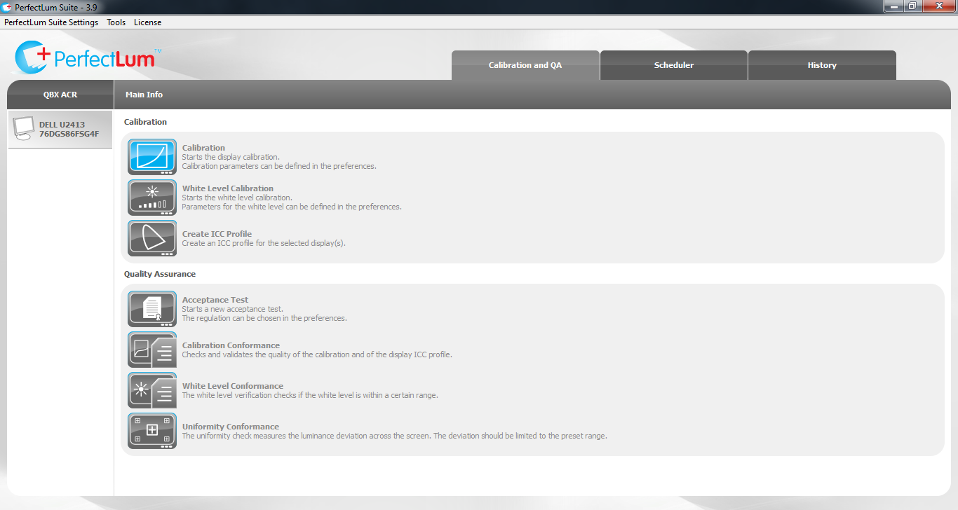
Figure 2. PerfectLum main window
IMPORTANT: Before starting the calibration, please warm up your display for at least 30 minutes.
Place the measuring device on the display and start the calibration process. Make sure no ambient light reaches the sensor. After calibration is finished, PerfectLum will provide a conformance report.
Step 5. Perform the QA acceptance test
The ACR acceptance test consists of two parts: a set of visual tests and a measurement part (a sensor is needed). To start the “Acceptance test” click “Acceptance Test” in the PerfectLum main window and simply follow the instructions given by the test wizard.
IMPORTANT: If you are running a demo version of the product, you will not get the detailed acceptance test report for your display. The generated report is a sample and does not show the real results of the performed test.
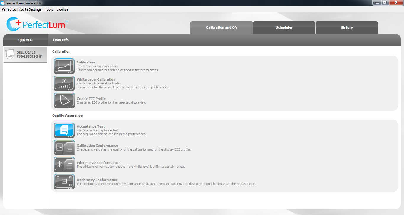
Figure 3. Automated acceptance test
The ACR guidelines require to perform visual constancy tests monthly and measurement constancy tests quarterly.
After the acceptance test is performed, PerfectLum will automatically generate schedules for the corresponding constancy tests.
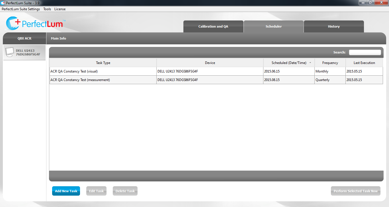
Figure 4. PerfectLum Scheduler
Step 6. Perform Constancy tests when they are due
PerfectLum will notify you when the tests are due. Click the “Perform Scheduled Tasks”’ button to carry out a scheduled task or “Remind Me In” to choose when you will be reminded again. When performing the tasks, simply follow the Test Wizard.
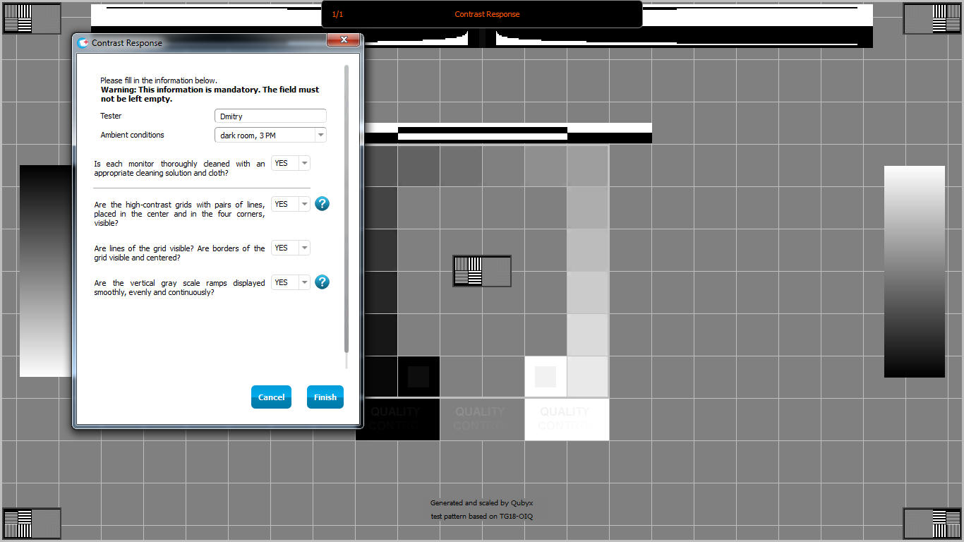
Figure 5. PerfectLum Test Wizard
Step 7. Get the ready-to-print pdf reports
PerfectLum generates a PDF report for each completed test that can be printed using a PDF reader. Each report will be saved in the history database.

Glossary
1. Analog signal – a form of information transmission in which the signal varies in a continuous manner and is
not limited to discrete steps.
2. Archive – a repository for digital medical images in a picture archiving and communications system (PACS), typically with the specific purpose of providing either short-term or long-term (permanent) storage of images. Erasable or nonerasable media may be used in an archive.
3. Bit (binary digit) – the smallest unit of digital information that a computing device handles. It represents off or on (0 or 1). All data in computing devices are processed as bits or strings of bits.
4. Bit depth – the number of bits used to encode the signal intensity of each pixel of the image.
5. Compression ratio – the ratio of the number of bits in an original image to that in a compressed version of that image. For example, a compression ratio of 2:1 would correspond to a compressed image with one-half the number of bits of the original.
6. CR (computed radiography) – a system that uses a storage phosphor plate contained in a cassette instead of a film-screen cassette. A laser beam scans the exposed plate to produce the digital data that is then converted into an image.
7. CRT (cathode ray tube) – an older technology monitor or display device used for viewing digital softcopy images. A CRT uses a controlled beam of electrons incident on a phosphor to generate a luminous image.
8. Data communication – all forms of computer information exchange. Data communication may take place between two computers in the same building via a local area network (LAN), across the country via telephone, or elsewhere by a wide-area network (WAN).
9. Data compression – methods to reduce the data volume by encoding it in a more efficient manner, thus reducing the image processing and transmission times and storage space required. These methods may be reversible (lossless) or irreversible (lossy).
10. DICOM (Digital Imaging and Communications in Medicine) – a standard for interconnection of medical digital imaging devices, developed and sponsored by the American College of Radiology and the National Electrical Manufacturers Association, consisting of a standard image format and a standard communications protocol.
11. Digital signal – a form of information transmission in which the signal varies in discrete steps, not in a continuous manner.
12. Digitize – the process by which analog (continuous value) information is converted into digital (discrete value) information.
13. Direct image capture – the capture or acquisition of digital image data that have been acquired in digital format by an imaging modality. The image produced from the data, regardless of the modality that produced it (CT, MRI, CR, US), should include the full spatial resolution and bit depth of the original.
14. Dynamic range – the difference in signal intensity, or frequency, between the largest and smallest signals a system can process or display. Increasing the number of bits per pixel in a digital image increases the dynamic range of the image.
15. File – a set of digital data that have a common purpose, such as an image, a program, or a database.
16. Grayscale – the number of different shades of levels of gray that can be stored and displayed by a computer system. The number of gray levels is directly related to the number of bits used in each pixel: 6 bits = 64 gray levels, 7 bits = 128 gray levels, 8 bits = 256 gray levels, 10 bits = 1,024 gray levels, and 12 bits = 4,096 gray levels.
17. Hardware – a collective term used to describe the physical components that form a computer. The monitor, CPU, disk drives, memory, modem, and other components are all considered hardware.
18. Image matrix size – The size of an image described as the number of rows and the number of columns of pixels.
19. Image sampling: Up-sampling – Small matrix images are typically sampled more finely than the acquired pixel spacing in order to increase the number of rows and columns and increase the presented size. Down-18 / Electronic Practice TECHNICAL STANDARD sampling – Large matrix images are typically sampled more coarsely than the acquired pixel spacing in order to decrease the number of rows and columns so that the full image area can be presented.
20. Irreversible compression – some permanent alteration of digital image data. This is sometimes referred to as lossy compression.
21. LCD (liquid crystal display) – a modern monitor or display device used for viewing digital softcopy images.
22. Lossless compression – see reversible compression.
23. Lossy compression – see irreversible compression.
24. Monochrome monitor – a computer display in which an image is presented as different shades of gray from black to white (see also grayscale).
25. Mouse – an input device that allows the computer user to point to objects on the screen and execute commands.
26. PACS – Picture Archiving and Communication System.
27. Phosphor – the coating on the inside of a CRT or monitor that produces light when it is struck by an electron beam.
28. Pixel (picture element) – the smallest piece of information that can be displayed on a CRT. It is represented by a numerical code within the computer and displayed on the monitor as a dot of a specific color or intensity. An image is composed of a large array of pixels of differing intensities or colors.
29. Protocol – a set of guidelines by which two different computer devices communicate with each other.
30. RAM (random access memory) – a type of temporary memory in a computer in which programs are run, images are processed, and information is stored. The amount of RAM that a computer requires varies widely depending on the specific application. Information stored in RAM is lost when the power is shut off.
31. Resolution – spatial resolution is the ability to distinguish small objects at high contrast. It is related to and in some cases limited by the pixel size. Contrast (grayscale) resolution is the ability of a system to distinguish between objects of the same size having different signal intensity. It is related to and in some cases limited by the bit depth.
32. Reversible compression – no alteration of original image information upon reconstruction. This is sometimes referred to as lossless.
33. Secondary image capture – the capture in digital format of image data that originally existed in another primary format (e.g., a digital image data file on a CT scanner, or a screen-film radiographic film) through the process of video capture or film digitization.
34. SMPTE – the Society of Motion Picture and Television Engineers.
35. Software – a name given to the programs or sets of programs that are executed on a computer
Part II
Routine quality assurance (QA) is necessary and essential to ensure the performance of medical displays. As mentioned above, according to the ACR guidelines, the evaluation includes visual (spatial resolution, display fidelity, contrast response, the viewbox luminance) and measurement (luminance response to the DICOM GSDF) tests. However, this manual process can be very time consuming. The second part of this paper describes how to achieve the compliance with the guidelines from ACR using a tool to automate the QA process, which aims to increase physicist efficiency, and improve the consistency of QA results by reducing human error.
Achieve a compliance in 7 easy steps with QUBYX PerfectLum.